Measuring Air
 For all modern engines, knowing the amount of air in the engine is vital for
clean, efficient and powerful running. Our Air/Fuel ratios guide in the reference section explains
what conditions are being looked for.
For all modern engines, knowing the amount of air in the engine is vital for
clean, efficient and powerful running. Our Air/Fuel ratios guide in the reference section explains
what conditions are being looked for.
There are a few ways to calculate how much air is in the engine but first, you need to understand
Volumetric Efficiency (VE). It's a simple ratio of how much air is in a cylinder, compared to how much there should be if
it was at normal atmospheric pressure. If a cylinder could hold 250ccs of air, and has 125ccs inside,
it would have a VE of 50%. This could also be expressed as having 1/2 Atmospheric pressure in the cylinder.
If the cylinder had 500ccs of air inside it (still the same 250cc capacity) it would have a VE of 200%.
To get more air in than it would take at Atmospheric pressure would require either clever tuning like "Ram Air" effects
or a Supercharger (the term "supercharger" also covers turbochargers).
To get 2x the volume of air into a space that only should take half that, the pressure will have to be double.
That's what Volumetric Efficiency is all about. How efficient an engine is in getting the a particular volume of air into the cylinder.
One method of measuring air is an indirect calculation by using a table of the VE of the engine. Manifold Air Pressure (MAP)
based ECUs check the rpms of the engine, the air pressure outside the engine, the air pressure inside the manifold, the air
temperature and other sensors and make a calculation based on these factors to find out how much air should be in each cylinder.
Once it has a figure, it will inject the right amount of fuel to get the Air/Fuel Ratio (AFR)
it needs. Making changes to an engine that is MAP based will alter all the values of the VE table and throw the fueling out.
It's for this reason, that MAP controlled engines need to be carefully modified and different VE tables and calculations programmed
into it when changes are made.
A better way to find out the amount of air in the engine is by measuring the flow of air into it.
Air Flow Meters
 Air Flow Meters directly measure the amount of air going through the intake.
Because of this, VE tables are not needed. The volume of air
can be calculated at any time and the correct fuel amount for the air present can be injected.
One of the earliest systems was known as the "Barn Door" or flapper Air Flow Meter.
With some clever engineering, an L shaped door was fitted across the Intake pipe. One leg of the L closed off the
intake, whilst the other swung into a damping chamber to the side. The airpath can be seen in the picture above with green highlighting
the normal flow path, and the purple area is the damping chamber.
Air Flow Meters directly measure the amount of air going through the intake.
Because of this, VE tables are not needed. The volume of air
can be calculated at any time and the correct fuel amount for the air present can be injected.
One of the earliest systems was known as the "Barn Door" or flapper Air Flow Meter.
With some clever engineering, an L shaped door was fitted across the Intake pipe. One leg of the L closed off the
intake, whilst the other swung into a damping chamber to the side. The airpath can be seen in the picture above with green highlighting
the normal flow path, and the purple area is the damping chamber.
When air was sucked in, the door would be pulled open against a spring, and the position of the door would be measured.
The ECU already has a table of how wide the door has to be for a certain amount of air, so the flow could be measured.
The second leg of the door would act as a damper, as it opened into an almost airtight chamber. This would help prevent the door swinging in
the wind like a barn door in a hurricane.
A clever feature of the second damper door was acceleration enrichment. When the throttle was snapped open, the door would slam open, overshooting the
calibrated air flow position, and send a signal higher than expected. That little burst of extra fuel is used for the Acceleration Enrichment,
before the spring and damper settles the door back at the correct position. An Intake Air Temperature Sensor (IAT) is also fitted to correct for the density of the air,
which varies with the intake temperature.
Clever as it is, the door is still quite a restriction in the air flow path, and being mechanical, the position contacts wear
over time. If the spring gets weak, it'll overfuel, or if the hinge becomes stiff, it'll run lean. That brings us to more electronic means.
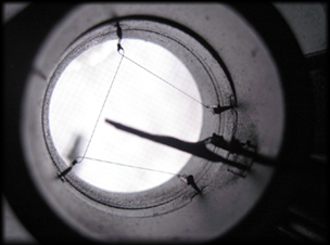 The next measurement sensor was the Hot Wire MAF(Mass Air Flow) meter. This uses a thin platinum filament
held in the airflow which is heated to about 300°C, which can be seen stretched across the centre metering tube in the picture to the right.
The resistance of the wire changes with its temperature, and the MAF holds the
uses the resistance to monitor the temperature, and will keep the temperature constant. The power needed to hold the temperature static is proportional to
the flow of air passing through, the MAF sends a signal to the ECU, and the ECU can then work out how much air is entering.
The next measurement sensor was the Hot Wire MAF(Mass Air Flow) meter. This uses a thin platinum filament
held in the airflow which is heated to about 300°C, which can be seen stretched across the centre metering tube in the picture to the right.
The resistance of the wire changes with its temperature, and the MAF holds the
uses the resistance to monitor the temperature, and will keep the temperature constant. The power needed to hold the temperature static is proportional to
the flow of air passing through, the MAF sends a signal to the ECU, and the ECU can then work out how much air is entering.
Colder air, or lots of air cools the wire, and higher signals are given. Effectively, the system measures Wind Chill on the wire. Colder air is denser (more oxygen in the same volume of cold air than in
warmer air) and the relationship is pretty close between lots of warm air or a small amount of cool air, but an Intake air temperature sensor is still used
just to perfect the reading.
The wire needs to be kept clean from dirt, so after switching off, it will activate a high temperature burn off mode to remove any oil traces or dirt,
but residues can still remain and knock the sensor out of balance.
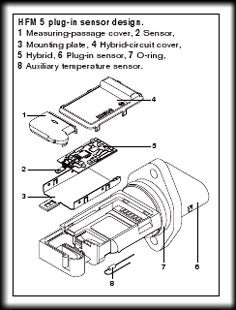 Heated Film meters were produced after this, using a small heated tab which fixed a number of problems with Heated Wire sensors. They were less fragile,
operated at a higher temperature which removed the need for a burn off stage, and also could now detect reverse air flow.
Heated Film meters were produced after this, using a small heated tab which fixed a number of problems with Heated Wire sensors. They were less fragile,
operated at a higher temperature which removed the need for a burn off stage, and also could now detect reverse air flow.
As mentioned in Intake Systems, turbulent air from an air filter too close to the Air Flow Meter could swirl around
and be measured more than once as it passes the sensor, and this would result in an incorrect air measurement.
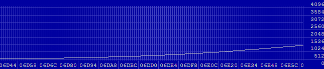
Both these systems only sample a small amount of air in the centre of the MAF tube. A linearisation table is programmed into the
ECU, calibrated from known measurements of clean airflow through the tube. Using a larger MAF would therefore have more air passing through the tube for the same signal.
Changes in Air Flow Meters may sometimes result in the ECU needing to be "recoded" to update the linearisation table for the different
characteristics of the new MAF. An example Linearisation Table is shown at the bottom of the page.
They still introduce a restriction into the intake path, but less so than the mechanical flapper meter, and the exact measurements outweigh
the drawbacks. Racing applications may often use Speed Density MAP systems, or Alpha-n (Throttle position and RPMS) as these have no restrictions, and are then
mapped to a VE table for maximum power.